
People
Presentations
- 2D QCA Examples (Animated)
A Quantum Game of Life
Companion Website
This page contains animations and complementary material for the 3D Quantum Cellular Automaton (QCA) described in the paper "A Quantum Game of Life" (arXiv). If you have any comments, questions or suggestions, please contact Jonathan Grattage.
-
Abstract
This research describes a three dimensional quantum cellular automaton (QCA) which can simulate all other 3D QCA. This intrinsically universal QCA belongs to the simplest subclass of QCA: Partitioned QCA (PQCA). PQCA are QCA of a particular form, where incoming information is scattered by a fixed unitary U before being redistributed and rescattered. Our construction is minimal amongst PQCA, having block size 2x2x2 and cell dimension 2. Signals, wires and gates emerge in an elegant fashion.
We are currently looking for students at Université Grenoble to implement this QCA as a masters project.
Signals and wires
Signals
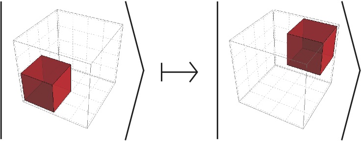
If a neighbourhood contains only one signal, ie only one cell is occupied, and the other seven are empty, then the signal is shifted by one in every direction, yielding a 3D diagonal propagation.
 |
|
|---|---|
| Signals move one cell along every axis to give diagonal propagation | |
 |
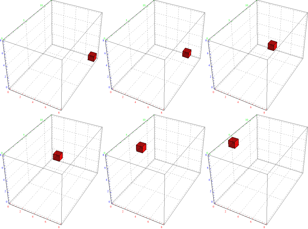 |
| Signal moving diagonally from near bottom left to far top right | Signal moving diagonally from far bottom right to near top left |
Barriers
Two or more occupied cells that share a common face form a barrier, which is intended as a stationary pattern. Such a barrier is stable for one partition as in the next partition it appears as two signals moving away from each other, and will then scatter. This can be avoided by extending beyond the current partition, by using at least four occupied cells. For example, a 2*2*1 block of cells which overlaps a partition and forms a barrier in each partition.
 |
 |
| An unstable barrier formed by two colliding signals | A stable barrier with an unstable barrier |
|---|
Walls
When two barriers, made of four occupied cells, form a square that fits within a partition, we say that they form a wall. A wall is able to redirect a fifth occupied cell, that shares only one face with the wall, which represents the incoming signal. They can be made stable as above, by extending them across partitions.
 |
|
|---|---|
| The wall bounce rule | |
 |
 |
| Two examples of signals bouncing off walls. | |
Qubits and quantum gates
Qubits
A qubit is formed by two parallel ``tracks'' of signals. A signal on the bottom track indicates a |0› state, whereas the top track indicates a |1› state. Qubits in superpositions are modelled by appropriate superpositions of the configurations.
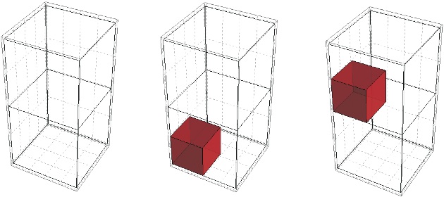 |
| No qubit is modelled as no signals (left), |0› is modelled as a signal on the lower track (centre), while a signal on the upper track models a qubit in state |1› (right). |
|---|
Hadamard
The Hadamard gate is a requirement for universal quantum computation. In order to achieve this typically quantum behaviour, a special meaning is attached to the interaction of a signal with a single two-cell barrier (defined above).
 |
|
|---|---|
| The Hadamard rule |
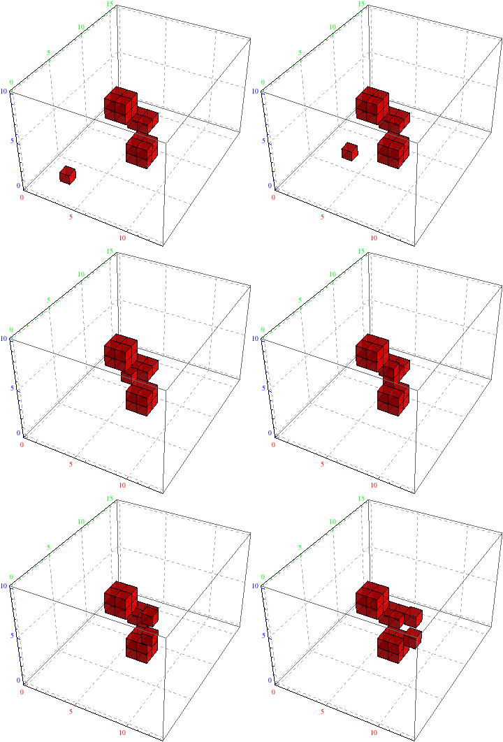
As all the rules we provide are rotation invariant, the unambiguity of the Hadamard rule may not be clear. To be unambiguous, we need be able to distinguish the |0› and |1› cases, and be able to distinguish the signal from the barrier. This can be done as follows: if the cube can be rotated such that all three signals are on a single face, forming an "L" shape, then the input to the Hadamard is |0›, and the signal is at the top of the L. If instead a lone occupied cell is on the top left of the furthest face, with a two-cell barrier along the bottom of the closest face, forming a dislocated L shape, then the input to the Hadamard is |1› and the signal is the isolated, top left cell.
To determine the what the output will be from the input, the signal must first be identified using the L configuration as discussed above. Starting from a |0› configuration, oriented with the L on the nearest face, to obtain the |0› output the signal is moved parallel to the barrier (to the right), to form a mirrored L. To obtain the orthogonal output, |1›, the signal is first slid along the barrier in the same fashion and then pushed onto the far face to form the dislocated, mirrored, L giving the output |1› state. These configurations are added together to create an equal superposition per the definition of the Hadamard operation. This gives the first rule shown above.
Starting with |1› input, a similar method is followed. To obtain the |1› output state, the signal is slid along the barrier, to form a dislocated, mirrored, L. To obtain the |0› state, the signal is again moved along the barrier, as previously, and then moved from the far face to the near face to form the mirrored L shape of the |0› case. These two states are then used to generate the equal superposition, with appropriate plus or minus phase, as shown in the second rule above.
 |
 |
| |0› goes to an equal superposition of |0› + |1› | |1› goes to an equal superposition of |0› - |1› |
|---|
 |
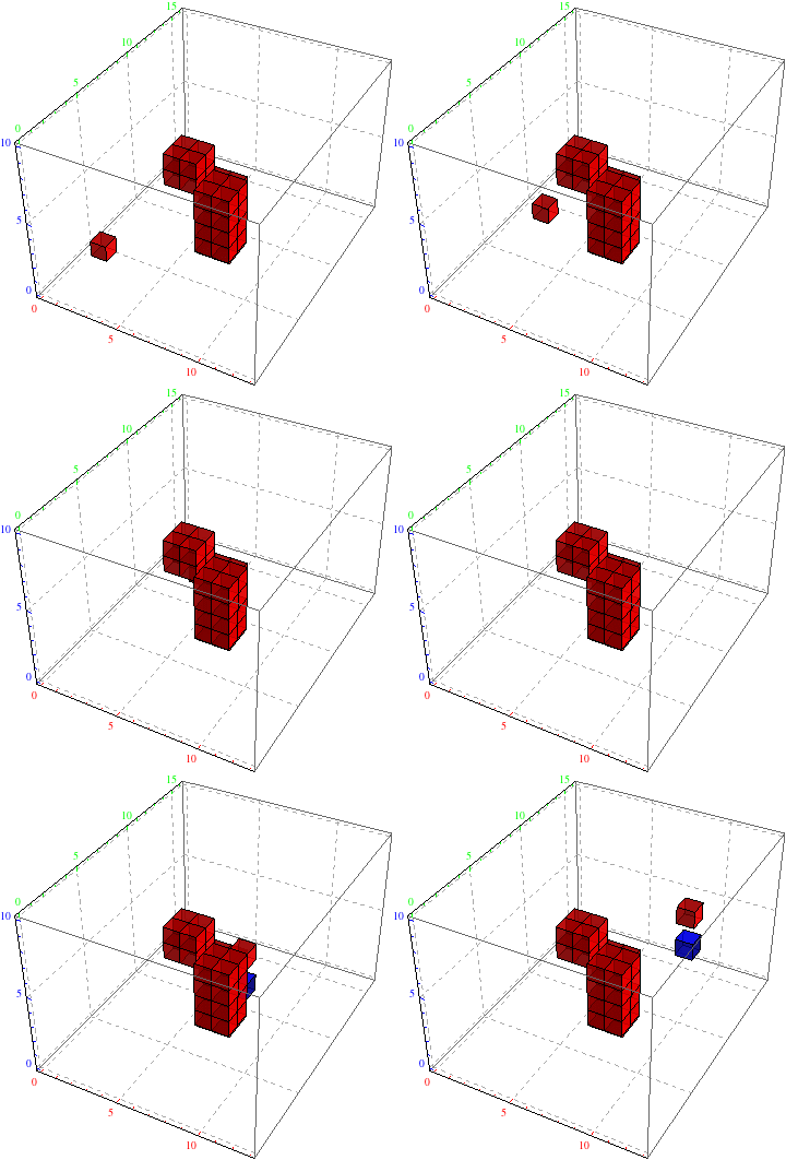 |
| The output can be redirected by the appropriate placement of walls | |
|---|---|
 |
 |
| |0› + |1› goes to |0› | |0› - |1› goes to |0› |
|---|
In the above figures superpositions are shown by superimposing the configurations upon each other to create a single animation, rather than duplicating the configurations following the rule given in the paper. Blue cells denote those with a negative phase, and amplitudes of +/- 1/√2 are not shown. The examples of superpositions given here are for illustrative purposes only and do not correspond to the actual system.
Controlled rotations
To encode a two qubit controlled gate, signal collisions, where two moving signals cross each other diagonally, will be interpreted as adding a global phase of e^(iπ/4).
 |
|---|
| The 'controlled-R(π/4)' rule |
This rule allows a controlled-R(π/4) operation to be defined, by redirecting the |1› (true) signal track so that they will cross each other in this way and then recreating the qubits by rejoining the |1› tracks back with the appropriate |0› tracks, using walls to redirect and delay signals as in the Hadamard case.
This same rule can also be used to implement a single qubit phase change operation by causing a control signal to loop such that it will intersect with the true track of the qubit, thus adding the global phase to the configuration. This needs to be correctly timed so that the tile implementing the single qubit rotation can be iterated, following the same reasoning as in Intrinsically Universal n-Dimensional QCA.
 |
| When two signals cross in this fashion, a global phase is added to the configuration. |
|---|
Rules and rotations
Under construction.
 |
 |